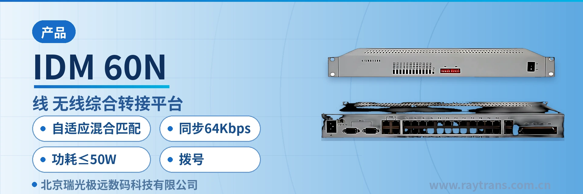
IDM-60N Wired and Wireless Integrated Interconnection Platform
2-channel radio, 24-channel terminal automatic interconnection, unattended operation, single-terminal unified control of two networks
The IDM-60N wired/wireless integrated interconnection platform is a dedicated communications device developed with digital technology to interconnect radio sets with wired terminal boxes and wired telephone networks. The interconnection system offers complete functions and excellent wired/wireless interconnection performance, and is suitable for a wide range of applications. The platform also supports long-distance wireless communication and features low equipment cost. It plays a command and dispatch role in communications operations for railways, military, public security, civil aviation airports, ports and wharves, and large and medium-sized enterprises, and has broad application prospects in communications and other fields.
The IDM-60N wired and wireless integrated switching platform is dedicated communications equipment that interconnects radio sets with wired terminal boxes and wired telephone networks, developed by Beijing Ruiguang Jiyuan Digital Technology Co., Ltd. (Raytrans). The equipment converts analog voice from the radio side through 2-wire/4-wire conversion and echo cancellation before sending it to the wired side, so a dispatcher can call wireless and wired users simultaneously from a single terminal. It is suitable for emergency communications and daily command and dispatch scenarios.
Key Specifications at a Glance: 24 wired terminals · 2 radio sets · 2 telephones · 4 E1 channels · adaptive hybrid matching · synchronous 64 Kbps · -10℃ to +55℃ · power consumption ≤50 W
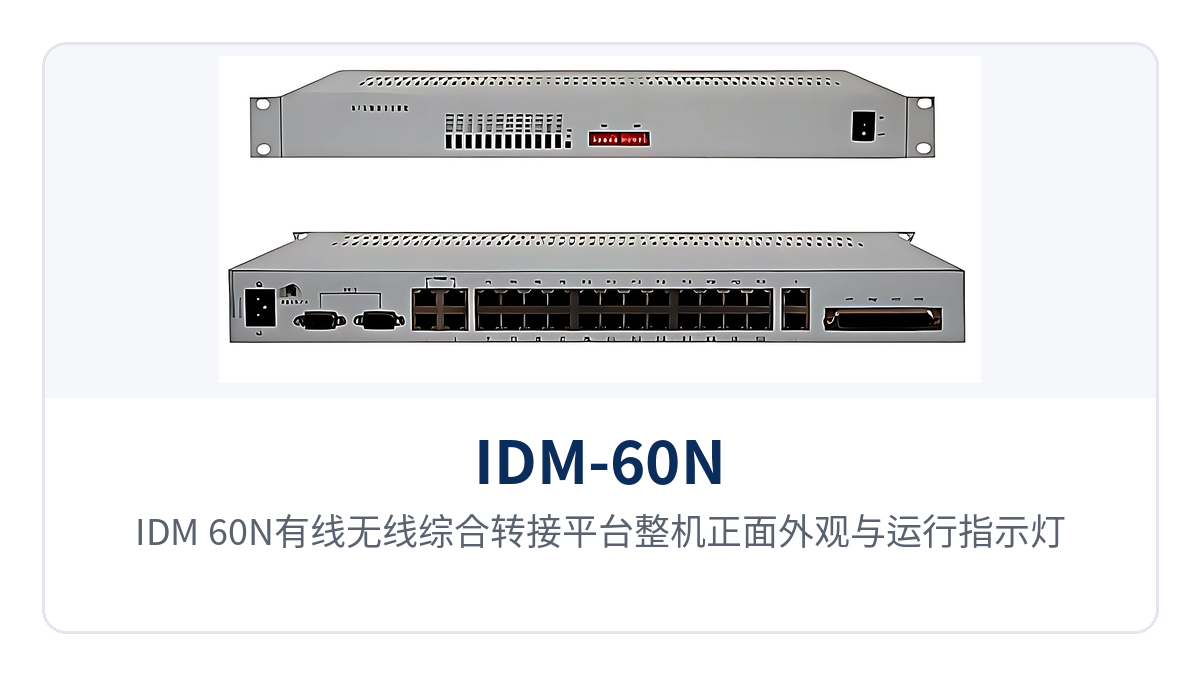
Figure 1: Front view and operating indicator LEDs of the IDM-60N wired and wireless integrated switching platform
The unit is a standard 19-inch 1U chassis measuring 440×230×45 mm, and can be installed directly into an existing 19-inch rack in a dispatch equipment room. Dispatch posts at railways, public security, military, ports, and large and medium-sized enterprises therefore do not need a separate cabinet for the switching equipment; the renovation work is concentrated on the cabling side, and equipment room space and power supply are calculated as for 1U equipment. As a command and dispatch system manufacturer, Raytrans has implemented unified access on both the wireless and wired sides on this platform, and its product showcase covers application directions such as emergency communications, military emergency communications vehicle solutions, and government private network optical fiber communication solutions.
What Problems Does the Wired and Wireless Integrated Switching Platform Solve
The two networks at a dispatch site have long each covered only part of the job: radio sets cover handheld and vehicle-mounted radios, while wired telephones cover fixed posts and higher-level offices, and users of the two types had to rely on manual call relay. A common practice is to assign a person beside the radio to listen and stand by, then manually connect the call to a wired telephone after receiving it, which is labor-intensive for the duty operator and carries a high risk of missed calls, especially at night and during busy periods.
The IDM-60N replaces this manual step with automatic switching by the equipment. The equipment uses digital signal processing technology and an echo canceller to overcome interference with wired voice detection caused by 2-wire/4-wire switching of radio signals, improving wired voice detection sensitivity; single-chip microcontroller control technology enables automatic switching between wired telephones and radio sets, changing the traditional listening-and-standby working mode of the radio.
After the renovation, the dispatcher no longer needs to stay beside the radio; one control terminal can manage multiple wireless and wired voice channels. The switching system can provide multiple control terminals simultaneously, so when dispatching seats are added by team, there is no need to equip each seat with another radio; the radio remains installed at its original antenna and feeder location, and changes are concentrated on the audio cable, control cable, and subscriber line side. For sites that need to connect to a government private network optical fiber communication solution, the equipment can interface with the existing transmission system through E1 or optical fiber channels, incorporating radio voice into the unified dispatching link.
What Are the Core Functions
The functions fall into categories of wireless access, wired access, automatic switching, recording, and O&M; the table below lists each function item and its on-site role. For selection, compare against the number of dispatching seats, the number of radio sets, and the number of voice channels; every item in the table can be confirmed on site through service dial testing and alarm indication.
| Function | Description |
|---|---|
| Radio set access | Provides 2 radio set interfaces and supports real-time intercommunication among radio sets of different frequencies |
| Wired terminal access | Provides 24 wired terminal interfaces and supports multiple desktop terminals |
| Telephone network access | Provides 2 telephone interfaces, giving fixed-line telephones and mobile phones remote dial-in command/monitoring means |
| E1 channel | Provides 4 E1 channels and can send services to remote stations through the existing transmission system |
| Automatic switching | Single-chip microcontroller control enables automatic switching between wired telephones and radio sets, replacing manual listening and standby |
| Hybrid network matching | Adaptive adjustment of hybrid network matching with loss greater than 26 dB; no manual calibration when connecting different telephones |
| Recording service | Provides recording service for all digital terminals, so call processes can be reviewed |
| Remote control | Transmission distance to the terminal controller reaches up to 6 km over twisted pair, so the control terminal can be far from the equipment room |
| Cascading expansion | Multiple units can work in cascade over long distances through E1 or optical fiber transmission, expanding coverage |
| Network management monitoring | Complete network management functions enable online real-time monitoring of equipment operating status |
| Interface expansion | Radio set interfaces, telephone interfaces, and wired terminal interfaces can be expanded |
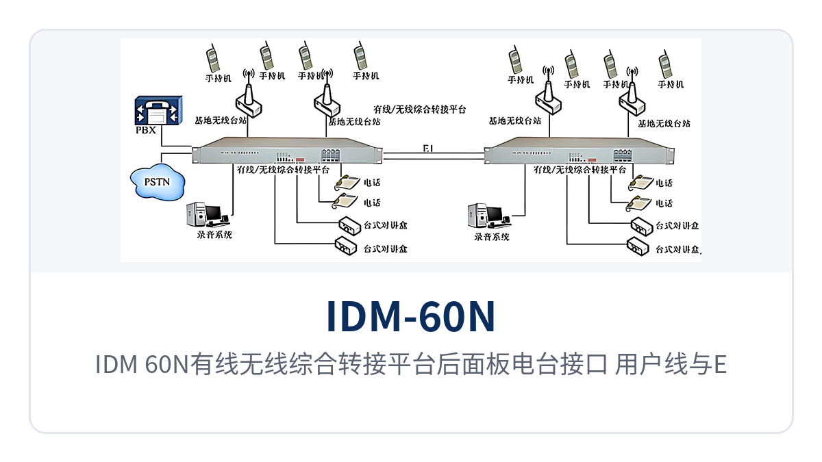
Figure 2: Rear panel layout of radio set interfaces, subscriber lines, and E1 interfaces on the IDM-60N wired and wireless integrated switching platform
Technical Specifications: Interface Levels, Dial-up Mode, and Transmission Rate
The specifications are listed in five groups: radio set interfaces, wired interfaces, telephone interfaces, V.24 interfaces, and unit conditions, with each item giving its specification and applicable conditions. When checking, first see whether the 600 Ω impedance and input/output levels on the wireless side can interface with the radios in service, then see whether the loop current on the wired side can drive the on-site telephones.
Radio Set Interfaces
| Item | Parameter/Specification | Description/Applicable Conditions |
|---|---|---|
| Input and output impedance | 600 Ω (balanced or unbalanced) | Interface with the radio audio port in balanced or unbalanced mode |
| Input level | -10 to +10 dBm | No external attenuation is needed if the radio audio output falls within this range |
| Output level | -35 to +10 dBm | Sent to the radio input; adjusted unit by unit according to on-site volume |
| Keying output | Relay contact | Used to control radio transmission; wire according to the radio keying wiring sequence |
Wired Interfaces
| Item | Parameter/Specification | Description/Applicable Conditions |
|---|---|---|
| Output level | -4.5 dBm (adjustable from -10 to +6 dBm) | Sent to the subscriber line; adjusted according to line length and telephone sensitivity |
| Input level | -4.5 dBm (adjustable from -10 to +6 dBm) | Voice level from the subscriber line; adjustable according to the on-site telephone |
| Interface mode | Subscriber line | Directly connects to common-battery telephones and desktop terminals |
| Off-hook loop current | ≥20 mA | Ensures the off-hook state of the telephone is reliably detected |
| Hybrid network matching | Adaptive adjustment, loss greater than 26 dB | Transmit/receive isolation for 2-wire/4-wire conversion, with no manual calibration |
| Dial-up mode | DTMF | DTMF dialing, consistent with conventional dispatch telephones |
Telephone Interfaces (FXO/FXS)
| Item | Parameter/Specification | Description/Applicable Conditions |
|---|---|---|
| Audio range | 300 Hz to 3400 Hz | Voice and fax are carried in the same voice channel |
| Compression | ITU G.711 A-law | Consistent with the encoding of existing PCM and switching equipment |
| Impedance | Three-element complex impedance 200 Ω + 560 Ω//0.1 μF | Values taken according to domestic subscriber line impedance specifications |
| Loop current | 25 mA per channel | Power feeding current, meeting the off-hook requirements of conventional telephones |
V.24 Interfaces and Unit Conditions
| Item | Parameter/Specification | Description/Applicable Conditions |
|---|---|---|
| Transmission rate | Asynchronous ≤9600 bps; synchronous 64 Kbps | Carries radio remote control, status, and private network data |
| Electrical characteristics | Complies with CCITT V.28 | Directly connects to existing V.24 data equipment |
| Power supply mode | AC 220 V | Takes the existing AC power supply in the dispatch equipment room |
| Overall power consumption | ≤50 W | UPS capacity is budgeted as low power, giving longer backup time |
| Operating temperature | -10℃ to +55℃ | Covers unattended equipment rooms in northern winters and temperature rise inside cabinets in summer |
| Relative humidity | 0 to 95% (non-condensing) | In humid areas, cabinet ventilation must be maintained to avoid condensation |
| Dimensions | 440×230×45 (mm) | 19-inch 1U chassis, 230 mm deep |
Differentiated Value: What Three Specifications Mean at a Private Network Site
The three capabilities correspond not to paper specifications but to three on-site matters: commissioning hours, data interfacing, and equipment room environment. The table below maps each capability to its direct impact at a private network site, which can be used to judge whether it matches the equipment room conditions, existing radios, and telephone models at the site.
| Differentiation Point | What It Means at a Private Network Site |
|---|---|
| Adaptive hybrid matching | Adaptive adjustment of hybrid network matching on the wired side with loss greater than 26 dB; no re-balancing when connecting telephones of different models, saving one step each for commissioning and telephone replacement |
| Synchronous 64 Kbps | The V.24 interface supports asynchronous ≤9600 bps and synchronous 64 Kbps and complies with CCITT V.28, so radio remote control units and existing data terminals can be connected directly |
| -10℃ to +55℃ | Operating temperature -10℃ to +55℃ and humidity 0 to 95% non-condensing allow continuous operation even in unattended points such as cabinets at intermediate stations and field equipment rooms |
| Power consumption ≤50 W | Overall power consumption ≤50 W; equipment room power supply and UPS capacity are calculated as for 1U equipment, so backup power can last longer after a power failure |
As the switching link in emergency communications and military emergency communications vehicle solutions, the IDM-60N can interconnect with the platform of a command and dispatch system manufacturer, bringing radio voice and wired dispatching seats into the same link; Raytrans provides a complete product showcase from equipment to cascading expansion, making it easy for users to configure flexibly according to site scale in a government private network optical fiber communication solution.
Typical Application Scenarios
The switching platform lands differently in different industries: railways value the connection between section radios and station telephones, public security and the military value multi-band radios converging into the command post, and ports and enterprises value the interconnection between operations area wireless and internal telephones. The following describes the networking approach and configuration points for three types of sites respectively; each solution is based on the standard interface configuration in the product showcase.
Railway Dispatch Communications: Connecting Section Radios and Station Telephones
Railway traffic and maintenance posts are scattered along sections, where handheld and vehicle-mounted radios are used for contact on site, while station duty rooms and dispatch offices rely on wired telephones to issue orders. The two sides originally relied on duty operators to relay messages verbally, which made the command chain long and prone to distortion in retelling. Elements such as train numbers and track numbers are easily misstated in verbal relay, and train operations demand high accuracy of instructions, so the relay step has long been a difficulty in on-site management.
The IDM-60N is installed in the station communications equipment room, connecting section radio voice to station subscriber lines, so the dispatch office can dial directly to reach section workers. The 4 E1 channels are uplinked through the existing transmission system, and the 6 km control distance over twisted pair allows the control terminal to be placed in the duty room rather than the equipment room.
For configuration, determine the number of radio set interfaces by the number of sections and the number of wired terminal interfaces by the number of duty seats. Where an E1 or optical transmission channel already exists between the station and the dispatch office, multiple units can work in cascade to expand coverage without laying separate control cables for each section. Such scenarios follow the same transmission approach as government private network optical fiber communication solutions, and existing optical transmission resources can be reused to achieve section coverage.
Public Security and Military Command Private Networks: Multi-Band Radios Converging into the Command Post
Public security and military on-site communications often use radios in multiple frequency bands simultaneously, and the command post also needs to send instructions to wired telephones and fixed posts. With different frequency bands and formats, duty operators previously had to switch back and forth among several radios. Calls in another frequency band may be missed during switching, and this gap is especially sensitive when handling emergencies.
The 2 radio set interfaces support real-time intercommunication among radio sets of different frequencies, so a commander can monitor two frequency bands simultaneously through one control terminal and join the call at any time. The 24 wired terminal interfaces can connect multiple desktop terminals, with command seats and duty seats sharing the same switching resources. This configuration is also a common form of military emergency communications vehicle solutions and can be deployed quickly in a vehicle-mounted rack.
Field command posts and mobile command vehicles are sensitive to power supply and environment; with overall power consumption ≤50 W and operating temperature -10℃ to +55℃, the unit can operate with AC 220 V power or a vehicle-mounted inverter power supply. When connection to the higher-level office telephone network is required, dialing in through the telephone interface enables remote command and monitoring, meeting the fast-connection requirements of emergency communications.
Port Terminals and Large and Medium-Sized Enterprise Dispatch: Interconnecting Operations Area Wireless and Internal Telephones
Ports and docks, mining operations and large and medium-sized enterprises have large operations areas with many duty posts: production dispatching relies on intercoms, while administrative and security posts use internal telephones. The two systems have no direct channel between them, so emergency repairs and emergency response depend on telephone notifications passed up level by level.
IDM-60N connects the radio sets in the operations area and the internal telephones on the plant site to the same platform. Dialing from the telephone side, the dispatch console can call field intercoms directly, and field calls can also land straight on the telephones in the dispatch room. Recording covers all digital terminals, and calls can be replayed afterwards, which makes it easier to review an incident and establish where responsibility lay.
Equipment rooms on plant sites are mostly unattended, and the temperature and humidity inside the cabinet fluctuate widely. The device has an operating temperature of -10℃~+55℃ and a humidity of 0~95% non-condensing; its 1U chassis can be installed in the existing 19-inch rack, and a retrofit only requires leading cables out from the radio audio port and the subscriber patch panel.
Deployment and Wiring: Five Steps on Site
On-site commissioning proceeds in five steps, ordered on the principle of cabling first, then levels, then services: do not move on to the next step until the readings of the previous step are confirmed. Each step leaves check items that can be verified, which reduces rework during joint commissioning and avoids a second site visit. At retrofit sites most of the cabling runs in existing cable racks, so confirm the spare wire pairs and terminal numbers before work starts and avoid occupying voice channels that are in service.
- Check the interface list: confirm the number of radio sets and the audio port type, the number of telephones and the number of E1 channels, and check each item against the ordered configuration.
- Connect the radio side: wire the radio audio output to the input port and the audio input to the output port, wire the keying line as a relay contact, and apply single-end grounding to the shield.
- Connect the wired side: terminate subscriber lines on the patch panel and check channel by channel that the off-hook loop current reaches 20mA or more.
- Adjust levels: set the radio-side input level within the -10~+10dBm range and the wired-side level to around -4.5dBm, and lock the settings after actual measurement of the speech volume.
- Dial test and recording: run a dial test of DTMF dialing, transfer and recording on each channel, and once the network management alarms have been checked and found clear, record the configuration and keep the wiring table on file.
Conclusion
The IDM-60N Wired/Wireless Integrated Switching Platform brings radio sets, wired terminals and the telephone network into one dispatching system in a single 1U device, replacing the previous practice of an operator watching the radio and transferring calls by hand with automatic switching. With 24 wired terminals, 2 radio sets, 4 E1 channels and a 6km control distance, together with adaptive hybrid matching, a wide temperature range and low power consumption, it suits dispatch equipment room renovation for railways, public security, the military and port enterprises.
Where a selection calculation is required according to the on-site radio set models, the number of telephones and the transmission channels, the radio audio port type, the number of duty operator seats and the environmental conditions of the equipment room can be provided, and the interface configuration and cascading networking approach are then determined on that basis. Once the number of interface channels, the control distance and the cascading links have been calculated together, the process moves on to commercial quotation and ordering.