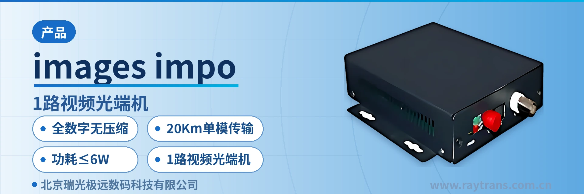
IDM-VDA100 1-Channel Video Optical Multiplexer
All-digital uncompressed, lossless picture quality, transparent data pass-through for PTZ commands, adjustment-free plug-and-play
The single-channel video series optical multiplexer is a compact optical fiber transmission product for video, data and other service signals, developed by our company using advanced all-digital uncompressed video technology and tailored to the security surveillance market. It can transmit up to
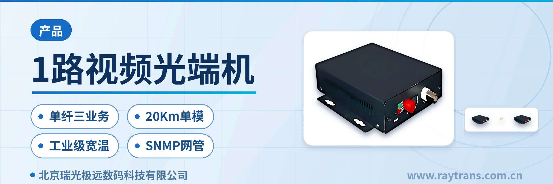
The IDM-VDA100 1-channel unidirectional video optical multiplexer is a single-channel video optical fiber transmission device developed by Beijing Ruiguang Jiyuan Digital Technology Co., Ltd. (Raytrans) using all-digital uncompressed video technology. It is used in pairs, with a transmitter and a receiver, to backhaul one channel of camera video over optical fiber in real time. As a typical 1-channel video optical multiplexer product, it samples analog video into a digital signal at the transmitter and sends it directly over the optical fiber, with no compression encoding in the link, and the receiver restores it to video output with lossless picture quality. The device belongs to the all-digital uncompressed video optical multiplexer series and is suitable for security surveillance video optical fiber transmission scenarios; it can also perform video lossless regenerative repeater tasks.
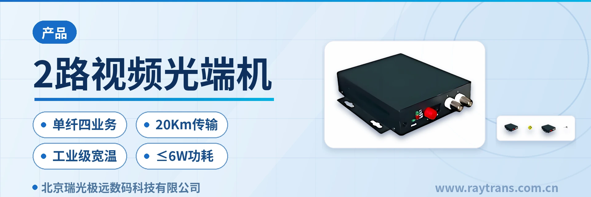
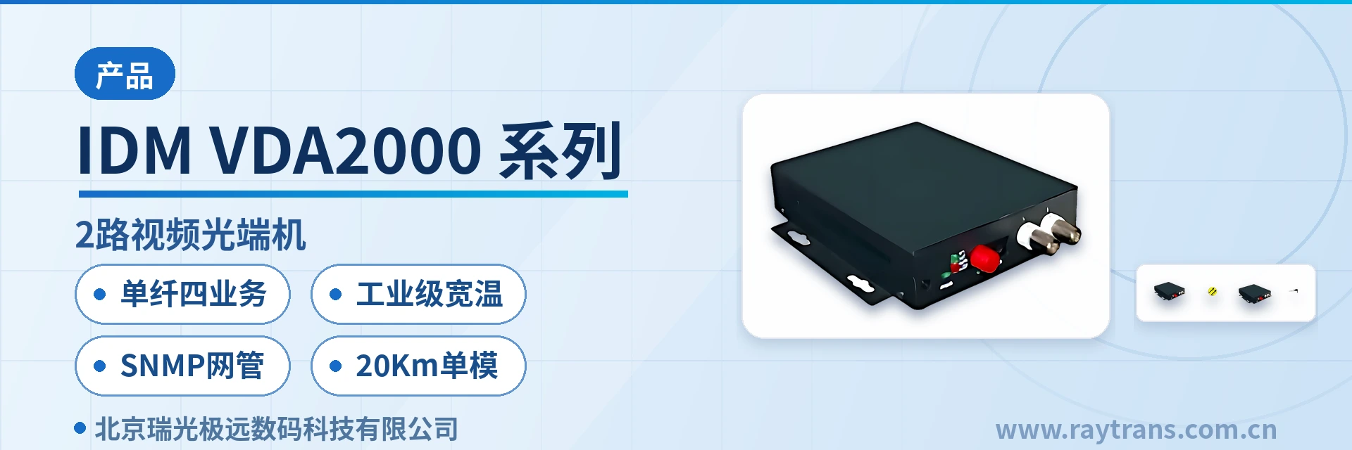
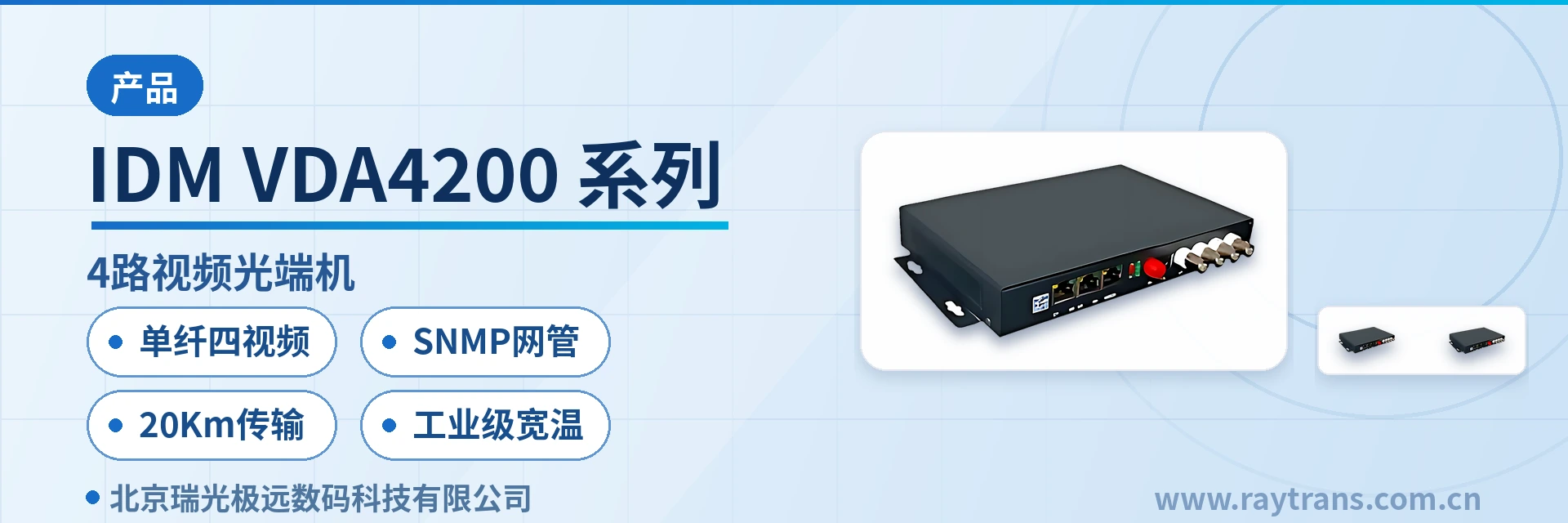
The device features an integrated multi-function design and can be installed directly in a site enclosure, a pole-mounted cabinet, or a weak-current box. The plug-and-play access mode means no electrical or optical adjustment is required on site. The optical module and core circuits use standard components, and the optical and electrical interfaces comply with international standards, adapting to different operating environments. As a professional optical multiplexer manufacturer, Raytrans continues the industrial-grade design approach of the Raytrans brand in this product, and its compact structure and interface layout are visible in the product showcase. For centralized management, an SNMP network management optical multiplexer version is optional, enabling remote status monitoring of video optical multiplexer devices.
Key Specifications at a Glance: 1-channel unidirectional video · video SNR ≥70 dB (weighted) · video bandwidth 0 Hz6.5 MHz · FC single-mode optical port (SC customizable) · single-mode 20 km · industrial grade -40℃+85℃ · overall power consumption ≤6 W
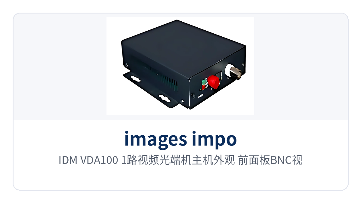
Figure 1: IDM-VDA100 1-channel video optical multiplexer main unit appearance — close-up of the front-panel BNC video ports and FC optical port
What is a 1-channel unidirectional video optical multiplexer? How does all-digital uncompressed transmission achieve lossless picture quality?
A 1-channel unidirectional video optical multiplexer is a pair of access devices that send camera video into optical fiber digitally and restore the output at the central side; the service direction is unidirectional, meaning images travel only from the site to the center. An all-digital uncompressed video optical multiplexer means the video signal, after analog-to-digital sampling at the transmitter, is transmitted directly in digital form over the optical fiber without compression encoding, and the receiver then performs digital-to-analog restoration, so the picture is not affected by the loss of detail caused by compression algorithms.
Picture quality is determined by several hard metrics of the video channel. With a sampling bit width of 8 bit and a video bandwidth of 0 Hz~6.5 MHz, it can fully carry video signals in formats such as PAL, NTSC, and SECAM; the video SNR is ≥70 dB (weighted), luminance non-linearity <3%, differential gain (DG) <0.7%, and differential phase (DP) <0.7°. These metrics support the positioning of the all-digital uncompressed video optical multiplexer for lossless picture quality restoration in security surveillance video optical fiber transmission.
Surveillance scenarios best demonstrate the value of uncompressed transmission. Compression encoding tends to produce block artifacts and ghosting on moving pictures and also introduces encoding and decoding latency, affecting evidence collection and real-time viewing; all-digital uncompressed transmission sends every frame of raw samples directly over the optical fiber, with stable detail and color restoration and no additional transmission latency.
The video interface is BNC, with an input/output impedance of 75 Ω (unbalanced), an input/output voltage of 1 VP-P (typical), and an input overload voltage of 1.5 VP-P (typical). It can connect directly to the video ports of cameras and monitors, and the existing 75 Ω video coaxial cable on site can be reused.
What functions does the 1-channel video optical multiplexer provide? Function and performance summary table
The functions of the IDM-VDA100 are divided into service channels, video quality, and O&M capabilities; the role of each function is shown in the table below. The capabilities listed are the basic capabilities under factory configuration; optional items are determined by model and ordering requirements, and service ports not selected are not installed at the factory.
Function | Description |
|---|---|
1-channel unidirectional video | Provides one unidirectional video channel; camera images are transmitted over optical fiber and restored at the central side, for real-time image backhaul from surveillance sites |
All-digital uncompressed | After sampling, video is sent over the fiber directly without compression encoding, so the picture is unaffected by compression loss and encoding and decoding latency, preserving original detail |
Broadcast-grade video quality | Video quality reaches broadcast-grade standards, with 8-bit sampling and a video bandwidth of 0 Hz~6.5 MHz, enabling high-quality transmission of both moving and still images |
Video format compatibility | Compatible with video formats such as PAL, NTSC, and SECAM, adapting to cameras and monitors of different formats |
Transparent data encoding | Uses transparent data encoding, compatible with the products of major camera manufacturers; PTZ and dome camera control commands can be passed through |
SNMP network management | Supports SNMP network management optical multiplexer capability, enabling the central side to perform real-time online monitoring of link devices and service operating status |
Video lossless regenerative repeater | Supports video lossless regenerative repeater, so long-link repeating introduces no additional compression loss |
Port protection and anti-interference | SMT surface-mount process; ports feature multiple protection against lightning and surge, with no electromagnetic interference (EMI) or radio frequency interference (RFI) |
Adaptive, adjustment-free | Automatically adapts to line conditions; no on-site electrical or optical adjustment is required during use, and it is plug-and-play |
Compact design | Compact structure, dimensions 144×138×30 (mm); can be installed in a site enclosure, a pole-mounted cabinet, or a weak-current box |
Key specifications: optical interface, video channel, data and audio, and power supply and environment
Optical link parameters determine whether the link works and how far it reaches, and also determine how on-site patch cords and optical cables are configured. As a 1-channel video optical multiplexer from the professional optical multiplexer manufacturer Raytrans, the IDM-VDA100 technical specifications for the optical interface are shown in the table below; the values are based on the conventional single-mode configuration, and multimode configurations are confirmed separately as ordering options.
Item | Parameter/Specification | Description/Applicable Conditions |
|---|---|---|
Interface type | FC (SC and others can be customized) | Optical port connector type, customized according to the optical fiber patch cords configured for the project |
Fiber mode | Single-mode (multi-mode optional) | Single-mode is the standard configuration; multi-mode is optional according to the optical cables already laid on site |
Receiver receive/transmit rate | 155Mbps/84M bps | 155Mbps in the receive direction, 84Mbps in the transmit direction |
Receiver receive/transmit wavelength | 1310nm/1550nm | Used in pair with the wavelength of the transmitter at the opposite end |
Transmitter receive/transmit rate | 84M bps/155M bps | 84Mbps in the transmit direction, 155Mbps in the receive direction |
Transmitter receive/transmit wavelength | 1550nm/1310nm | Used in pair with the wavelength of the receiver at the opposite end |
Transmit optical power | -15~-8dBm | Output optical power range of the transmitter |
Receiver sensitivity | Better than -32dBm (1310nm) | Used to determine the available optical power margin of the link |
Transmission distance | 20Km; long-distance optical modules can be installed for longer-distance optical fiber transmission | Based on single-mode fiber configuration |
The specifications of the video channel directly correspond to picture quality and are also items frequently spot-checked during project acceptance. The parameters of the video channel are listed one by one in the table below. The sampling accuracy and distortion specifications are given on a weighted basis and can be directly compared with the port specifications of cameras and monitors.
Item | Parameter/Specification | Description/Applicable Conditions |
|---|---|---|
Interface type | BNC | Video port for connecting cameras and monitors |
Video sampling bit width | 8bit | A/D sampling accuracy |
Video bandwidth | 0Hz~6.5MHz | Covers the video bandwidth of PAL, NTSC and SECAM formats |
Luminance non-linearity | <3% | Video transmission linearity specification |
Differential phase (DP) | <0.7° | Chroma phase distortion specification |
Differential gain (DG) | <0.7% | Chroma gain distortion specification |
Input overload voltage | 1.5VP-P (typical) | Overload level allowed at the video input |
Input/output voltage | 1VP-P (typical) | Standard video signal level |
Input/output impedance | 75Ω (unbalanced) | Consistent with the impedance of conventional video coaxial cables |
Video SNR | ≥70dB (weighted) | Weighted SNR specification, reflecting the noise level of surveillance video |
The data and bidirectional audio channel parameters that can be added according to the model are listed in the table below. Data channels are used for PTZ and speed dome control, and audio channels are used for intercom between the center and the site. Both types of services are added according to the model. If the corresponding service is not selected, the port group is not configured at the factory, and it can be identified by the front panel markings during wiring.
Item | Parameter/Specification | Description/Applicable Conditions |
|---|---|---|
Data interface type | RJ-45 | Data port connector |
Data type | RS-232, RS422 (4-wire), RS485 (2-wire) | Select the wiring mode according to the interface type of the on-site control device |
Audio interface type | RJ45 | Audio input/output connector |
Audio sampling bit width | 16bit | A/D and D/A sampling precision |
Audio sampling frequency | 32KHz | Audio sampling clock |
Audio input/output impedance | ADC:100KΩ / DAC:10KΩ | The input and output impedances differ; connect according to the port markings |
Audio input/output voltage | 1.5VP-P (typical) | Audio signal level |
Audio bandwidth | 20Hz~20KHz | Covers the frequency band of human voice and conventional audio services |
Audio SNR | ≥90dB | Audio channel SNR specification |
Total harmonic distortion | <1% | Audio nonlinear distortion specification |
Power supply, environmental and structural parameters determine where the device can be installed and whether an industrial-grade configuration is required. The power supply, environmental and structural parameters of the IDM-VDA100 are listed in the table below. The temperature ranges of the conventional model and the industrial-grade model differ, so the selection must match the installation position.
Item | Parameter/Specification | Description/Applicable Conditions |
|---|---|---|
Power supply mode | AC220V/DC-48V | Selected according to the power supply conditions of the equipment room and the site |
Overall power consumption | ≤6W | Power consumption of a single-end device; DC-48V can be taken directly from the site DC distribution panel |
Operating temperature | -15℃~+65℃ | Operating temperature range of the conventional model |
Storage temperature | -25℃~+75℃ | Storage temperature in non-operating state |
Industrial-grade temperature | -40℃~+85℃ | Industrial-grade wide-temperature configuration, suitable for unattended cabinets in the field |
Relative humidity | 0~95% (non-condensing) | Humidity conditions of the operating environment |
Product dimensions | 144×138×30 (mm) | Length × depth × height |
How to Choose Between a 1-Channel Video Optical Multiplexer and a Multi-Service Optical Multiplexer?
To choose between a 1-channel video optical multiplexer and a multi-service optical multiplexer, first look at the number of services to be backhauled at a single site. When only 1 channel of image is needed, a single-channel device costs less; only when control, intercom, Ethernet, or even voice and E1 are required in addition to video is a multi-service optical multiplexer or a centralized access platform needed.
Within the IDM-VDA series, models are distinguished by service combination. The three configurations have identical video channels and differ only in whether data and audio channels are present, as shown in the table below. If the service requirements are unclear, judge by whether the site needs on-site intercom and whether PTZ control is required.
Service requirement | Corresponding model and configuration | Typical Use |
|---|---|---|
Backhaul 1 channel of video only | IDM-VDA100, 1-channel unidirectional video | Sites that only need to upload images |
PTZ and speed dome control in addition to video | IDM-VDA110, 1-channel unidirectional video + 1-channel data | Video + PTZ or speed dome control |
On-site intercom in addition to video and control | IDM-VDA111, 1-channel unidirectional video + 1-channel data + 1-channel bidirectional audio | Complete link for three services over a single fiber |
In addition to the number of service channels, selection also requires checking three on-site conditions. Link length is calculated on a 20 km single-mode baseline; where it is exceeded, a long-distance optical module is fitted. Where the installation position is an outdoor cabinet or an equipment room without air conditioning, choose the industrial-grade -40 °C to +85 °C configuration. Power supply is selected between DC-48 V and AC 220 V according to site conditions.
When a single site carries more than one video channel, or when telephone, E1, Ethernet and other services need to be aggregated to the center together, a multi-service optical multiplexer and a centralized access platform are more suitable. Such equipment scales by boards and service cards, and the central side can be used together with multiple single-channel devices to form hierarchical networking.
How Far Can a Video Optical Multiplexer Transmit? How to Calculate Transmission Distance and Optical Power Margin
The standard answer to how far a video optical multiplexer can transmit is 20 km single-mode transmission. The link is configured for 20 km single-mode, based on single-mode fiber, 1310 nm/1550 nm wavelengths and FC optical ports; when the project requires a longer distance, a long-distance optical module can be fitted for extension, while multimode fiber is an optional configuration selected according to the optical cable already laid on site.
Whether the link is sufficient must be judged by optical power. The transmit optical power at the transmitter is -15 to -8 dBm, and the receiver sensitivity at the receiver is better than -32 dBm (1310 nm); the difference between the two is the available optical power margin. In actual projects, optical fiber attenuation, splice point loss and mating connector loss must also be included and calculated section by section; only with sufficient margin can a weak optical link remain stable.
Distance and image quality do not conflict. The video channel bandwidth is fixed at 0 Hz to 6.5 MHz, and digital signals transmitted over optical fiber do not accumulate analog noise with distance; on a 20 km link, the signal-to-noise ratio can still be delivered to the video SNR ≥ 70 dB (weighted) specification, and the image does not turn gray or blurry as distance increases.
There are three common causes of distance overruns in projects: the actual optical cable length exceeds the design, too many splice points cause excessive attenuation, and patch cord end face contamination or too small a bend radius. The troubleshooting order is to first measure the received optical power, then check the attenuation records, and then inspect the end faces and patch cords.
How to Wire a Video Optical Multiplexer? Connection Order for BNC, RJ45 and FC Optical Ports
For how to wire a video optical multiplexer, under the factory configuration you only need to connect service cables according to the port markings, with no on-site electrical or optical adjustment required. Before wiring, check the model and optical wavelength configuration of the devices at both ends to avoid transmit/receive pairing errors. The following order is recommended to reduce the risk of end face contamination caused by repeatedly plugging or unplugging the optical ports.
First connect the camera and monitor to the BNC video ports, and confirm that the video cable is 75 Ω coaxial cable and that the connectors are crimped securely.
Then connect the data and audio ports according to the model; wire the data cable according to RS-232, RS422 (4-wire) or RS485 (2-wire).
Connect the FC optical port patch cords, check wavelength pairing at the transmit and receive ends, tighten the connectors fully, and leave sufficient fiber bend radius.
Check the power supply mode and voltage; AC 220 V and DC-48 V must not be mixed, and power-on is left as the final step.
After power-on, check the optical link and video output status; once the image is normal, the service can be enabled.
The connected object and wiring key points of each port are shown in the table below; during installation, check each port against the front panel markings. Cables connected to the wrong port are often discovered only at the power-on commissioning stage, and rework costs more than checking beforehand. Optical fiber patch cords are recommended to be connected with the power off, reducing end face contamination and accidental contact.
Port | Connected to | Wiring key points |
|---|---|---|
BNC video port | Camera / monitor | 75 Ω unbalanced, input/output voltage 1 Vp-p (typical), use 75 Ω video coaxial cable |
RJ-45 data port | PTZ controller / control keyboard / decoder | Select RS-232, RS422 (4-wire) or RS485 (2-wire) according to the device interface type |
RJ45 audio port | Intercom microphone / speaker | Input impedance ADC: 100 kΩ, output impedance DAC: 10 kΩ; connect according to the port markings |
FC optical port | Optical fiber patch cord / optical cable | Single-mode (multimode optional), SC and other interface types can be customized; note wavelength pairing at the transmit and receive ends |
Power port | AC 220 V / DC-48 V | Selected according to equipment room and site power supply conditions; overall power consumption ≤ 6 W |
Typical Applications
Security Surveillance System Integration Projects
At surveillance sites in industrial parks, plants and commercial complexes, integrators often encounter insufficient coaxial cable distance and fully occupied cable trays and ducts. IDM-VDA100 connects one camera at the site side and sends the image back to the surveillance center over a single optical fiber; the receiver outputs directly to a monitor, DVR or encoding device, making it a product showcase solution with simple structure and controllable investment in security surveillance video optical fiber transmission.
The optical fiber link is free from electromagnetic interference (EMI) and radio frequency interference (RFI), the image is unaffected by variable-frequency equipment and power cables, and no repeater amplifier is needed between the site and the center. The device is plug-and-play; the integrator only needs to connect the video cable and optical patch cord on site, keeping commissioning time controllable.
Rail Transit and Expressway Electromechanical Systems
Surveillance sites at toll stations, tunnel portals, interchanges and roadside cabinets are distributed along the line; cabinets are hot in summer and cold in winter, and the cost of a maintenance visit is high. IDM-VDA100 operates over the industrial-grade -40 °C to +85 °C wide temperature range and under relative humidity of 0 to 95% (non-condensing), suitable for outdoor cabinets and unattended sites.
With overall power consumption ≤ 6 W, DC sites can draw DC-48 V directly, while AC cabinets use AC 220 V, so sites do not need to modify the power supply specifically for the device. The device supports SNMP network management, so O&M personnel can see link and service status from the central side without waiting for an inspection to discover a link interruption.
Electric Power and Energy Substations and Unattended Stations
The distance between cameras and the main control room at substations, switching stations and pumping stations is often several kilometers; the electromagnetic environment inside the station is strong, and the power supply is mainly DC. For the substation video surveillance optical multiplexer, IDM-VDA100 is selected to send images back to the main control room or centralized control station over single-mode fiber; the transmit and receive ends are electrically isolated, and the ports provide multiple protection against lightning and surge.
With dimensions of 144 × 138 × 30 (mm), the device can be installed directly in the station's communications cabinet and is plug-and-play, requiring no on-site adjustment when put into operation. Overall power consumption ≤ 6 W and a direct DC-48 V supply also make recovery after power failure and inspection simpler for the site.
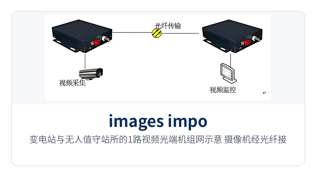
Figure 2: Networking schematic of the 1-channel video optical multiplexer for substations and unattended stations; the camera is connected to the central equipment room over optical fiber
Conclusion
IDM-VDA100 1-channel video optical multiplexer sends one camera image over optical fiber in an all-digital uncompressed video optical multiplexer manner, with video SNR ≥ 70 dB (weighted) and lossless image restoration; 20 km single-mode transmission together with receiver sensitivity better than -32 dBm keeps weak optical links stable, fully meeting the high requirements of security surveillance video optical fiber transmission for product showcase results.
Industrial-grade -40 °C to +85 °C wide temperature operation and overall power consumption ≤ 6 W support long-term operation at unattended sites in the field. When selecting a 1-channel video optical multiplexer for security surveillance, rail transit and electric power and energy projects, you can choose among the 100, 110 and 111 configurations according to the number of services at a single site; the specific optical module distance, interface type and power supply mode can be confirmed with the optical multiplexer manufacturer based on on-site conditions. Raytrans can provide SNMP network management optical multiplexers and video lossless regenerative repeaters and other supporting solutions, facilitating video optical multiplexer product showcase and system integration interfacing.