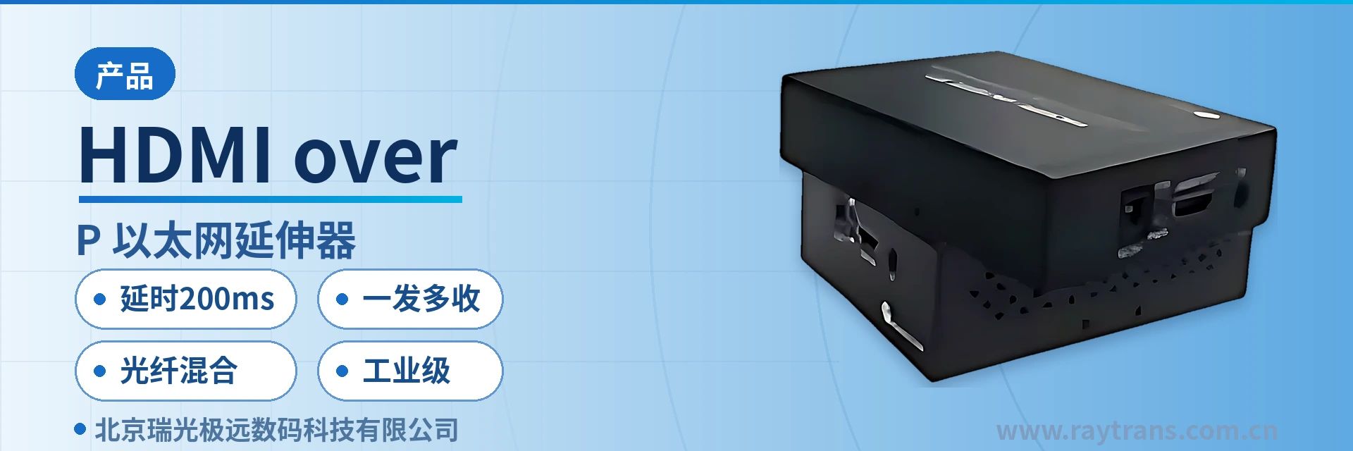
HDMI over IP Ethernet Extender
Cross-multi-layer switch, same VLAN one-to-many, five types of video interfaces over one cable
The Ethernet extender is a transmitter developed by our company using internationally advanced image processing chips, featuring high bandwidth and high-definition picture quality, and capable of transmitting HDMI, DVI, VGA, SDI, and CVBS video signals across multiple switches.
IDM-HD680X-DT/R is a cross-switch Ethernet extender developed by Beijing Ruiguang Jiyuan Digital Technology Co., Ltd. (Raytrans), used to convert HDMI, DVI, VGA, SDI, and CVBS video signals into high-bandwidth IP data, transmit them across multiple switches over Ethernet, and then restore them to high-definition images at the receiver. As a professional optical multiplexer manufacturer, Raytrans's product showcase in the video transmission field covers the complete chain from video optical multiplexers to industrial-grade network equipment.
The device is used in pairs, with the transmitter and receiver connected near the video source and the display end respectively, and the entire link in between carried by switches. In addition to video, separate audio, RS232/485 data, and IR infrared channels are provided, with image quality up to 1080P and end-to-end latency of less than 200 ms. Under the same VLAN, multiple receivers can simultaneously play the same image, and with a distributed IP matrix, arbitrary switching of thousands of images can be achieved. This solution can coordinate networking with video optical multiplexers and optical multiplexer equipment, and is also suitable for on-site network environments built by industrial Ethernet switch manufacturers.
Key Specifications at a Glance: 1080P HD · Latency <200 ms · Cross-switch · One-to-many under the same VLAN · Ethernet + optical fiber hybrid · Independent audio and RS232/485/IR
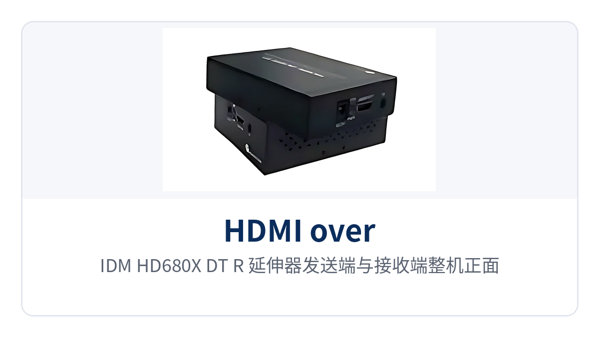
Figure 1: Front appearance of the IDM-HD680X-DT/R extender transmitter and receiver units, with a close-up of the power and link indicator LEDs
What kind of device is this cross-switch Ethernet extender?
The core of a cross-switch Ethernet extender is to carry video as network data rather than modulating the signal directly onto a point-to-point line. The transmitter encodes video from HDMI and other interfaces into IP packets, switches forward them according to ordinary Ethernet rules, and the receiver then decodes and restores them into a picture using an image processing chip. The video stream can therefore pass through multiple levels of switching nodes across the access layer, aggregation layer, and core layer, free from the length limits of a single cable segment and the topology of a point-to-point link. From a product showcase perspective, such devices belong to the same video transmission family as video optical multiplexers, but follow the Ethernet switching path rather than the point-to-point optical modulation path.
The switches along the transmission path perform only Layer 2 forwarding, and the video stream propagates within the same broadcast domain partitioned by VLAN. In engineering practice, the transmitter is connected to an access switch and the receiver to an aggregation or core switch, and the picture can still be restored normally after passing through several levels of switching. This feature makes the extender's cabling logic consistent with that of the office network: the construction team can lay patch cords and patch panels according to structured cabling standards, without laying a dedicated link for video. For engineers accustomed to solutions from optical multiplexer manufacturers, this cross-switch Ethernet extender offers a networking approach complementary to optical multiplexers.
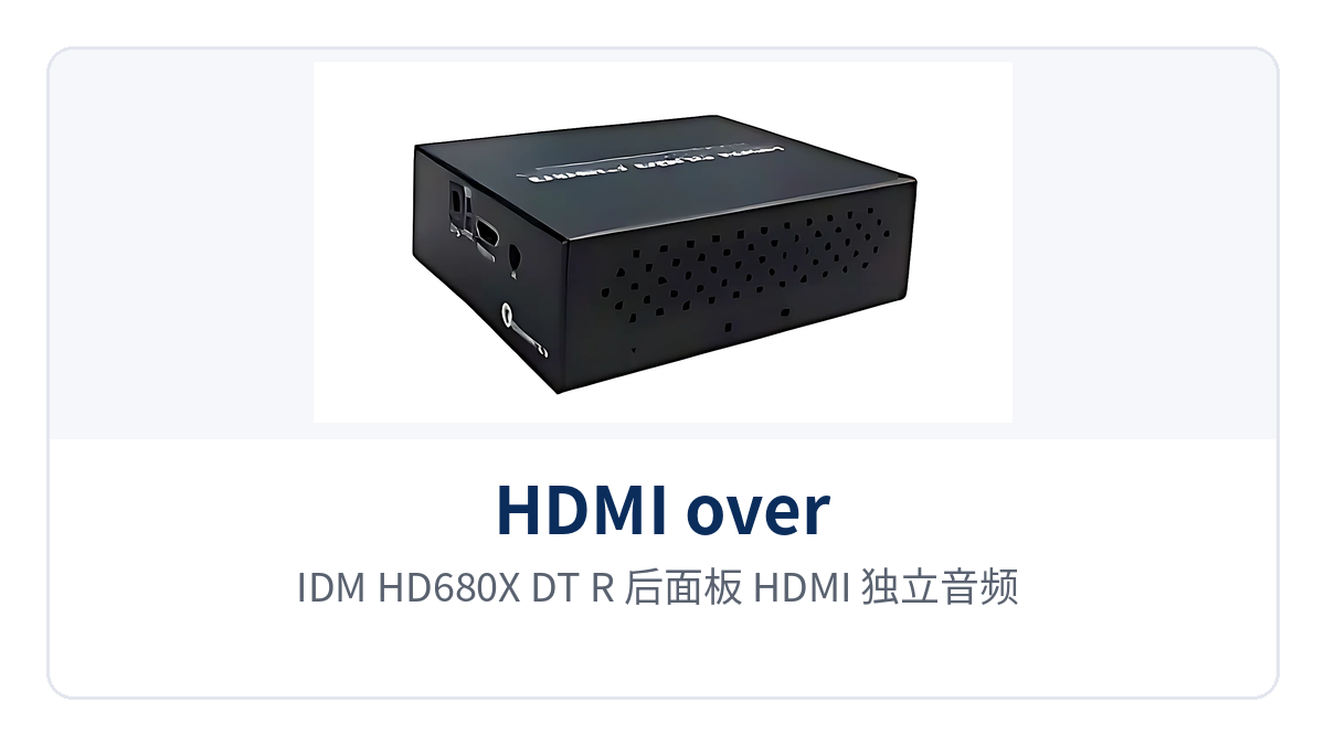
Figure 2: Rear panel layout of the IDM-HD680X-DT/R with HDMI, independent audio, RS232/485, and Ethernet interfaces
Knowledge block: IP-based transmission of HD video consists of three stages: encoding, switching and forwarding, and decoding. The four interface types HDMI, DVI, VGA, and SDI are handled uniformly on this device, with image quality up to 1080P and compatibility with formats such as 720P, 1080i, and 1080P. After video is converted to IP data, it is queued and forwarded as Ethernet frames; latency mainly comes from these three stages, and the overall link specification is less than 200 ms.
Core Functions and Their Roles
The device's functions center on four aspects: video interface compatibility, multi-service simultaneous transmission, networked networking, and industrial-grade operation, each corresponding to an action that can be verified on site. The table below lists function items and their roles row by row. During selection, confirm item by item against the site's interface types, number of display ends, and intermediate links; for configuration items not covered in the documentation, confirm with the manufacturer on a project basis rather than inferring from similar devices.
| Function | Description |
|---|---|
| Video interface compatibility | One device covers five types of video signals—HDMI, DVI, VGA, SDI, and CVBS—with HD image quality up to 1080P and compatibility with formats such as 720P, 1080i, and 1080P. |
| Networked extension | Video is converted to IP data and transmitted over Ethernet, capable of crossing multiple switches; link length is calculated based on the number of switch cascading levels and the length of optical fiber segments. |
| One-to-many | Under the same VLAN, one transmitter can correspond to multiple receivers playing the same image simultaneously, and the number of receivers can be increased as needed. |
| Distributed IP matrix expansion | Multiple transmitters and receivers are incorporated into the same management platform, and with a distributed IP matrix, arbitrary switching of thousands of images can be achieved. |
| Independent audio channel | Audio and video are transmitted separately, making it easy to feed sound independently into sound systems, power amplifiers, or conference sound reinforcement systems. |
| Data channel | RS232/RS485 data interfaces are provided, and control commands and status data are transmitted over the same network as video, eliminating separate cabling. |
| IR infrared control | IR infrared backhaul is supported, so the signal source device at the remote end can be operated with a remote control at the display end. |
| Ethernet and optical fiber hybrid | Electrical-port Ethernet segments and optical fiber links can be mixed on the same service chain, with optical fiber for long-distance segments and network cable for nearby ends. |
| Industrial-grade design | Supports long-term uninterrupted operation and adapts to complex environments such as equipment room cabinets, weak-current rooms, and on-site equipment boxes. |
Technical Specifications and Interface Specifications
Technical specifications are listed in four groups: video, network, control, and electrical, with nominal values taken from product documentation. For electrical items not given in the product documentation, this table notes that the accompanying technical documentation shall prevail; during on-site verification, do not substitute figures from similar devices, and do not treat ordering configurations as default configurations.
| Item | Parameter/Specification | Description/Applicable Conditions |
|---|---|---|
| Video interface | HDMI, DVI, VGA, SDI, CVBS | One device is compatible with five types of video signals; select the corresponding interface according to the on-site signal source |
| Video resolution | 1080P | HD image quality up to 1080P, compatible with formats such as 720P, 1080i, and 1080P |
| Video transmission latency | Less than 200 ms | End-to-end specification for high-speed Ethernet transmission, measured over the entire link |
| Transmission network | Ethernet, supporting multi-layer switching | Video is forwarded as IP data through switches and can cross multiple levels of switching nodes |
| Networking approach | One-to-many under the same VLAN | A single transmitter corresponds to multiple receivers playing simultaneously; both ends must be in the same VLAN |
| Expansion capability | Thousands of channels switching with a distributed IP matrix | The number of channels is planned according to the matrix scale and switching network capacity |
| Audio | Independent audio channel | Transmitted separately from video, facilitating independent connection to a sound reinforcement system |
| Data interface | RS232/RS485 | Control data is transmitted over the same network as video; the interface form is confirmed according to the ordering configuration |
| Control interface | IR infrared | The display end controls the remote signal source via remote control; the receiver requires an infrared receiver head |
| Transmission medium | Ethernet cable + optical fiber hybrid | Optical fiber for long-distance segments, network cable for nearby ends; the medium is switched on the switch side |
| Operating mode | Industrial grade, long-term uninterrupted operation | Suitable for continuous operation in equipment rooms, cabinets, and on-site weak-current environments |
| Power supply and power consumption | Not yet recorded in the knowledge base; subject to the accompanying technical documentation | Verify the power supply mode and overall power consumption against the ordering configuration and device label |
| Dimensions and installation | Not yet recorded in the knowledge base; subject to the accompanying technical documentation | Confirm the cabinet or desktop installation method according to the ordering configuration |
| Operating temperature and humidity | Not yet recorded in the knowledge base; subject to the accompanying technical documentation | Confirm with the manufacturer when on-site conditions exceed normal equipment room conditions |
Typical Application Scenarios
The applicability of the extender depends on the existing network conditions on site rather than the video interfaces themselves. In three types of occasions—industrial private networks and industrial park security, rail transit and energy and electric power, and unattended sites and long-distance links—the common factor is that switches or optical fiber separate the video source from the display end, making rewiring for video costly and time-consuming. The following describes networking conditions and configuration points by scenario.
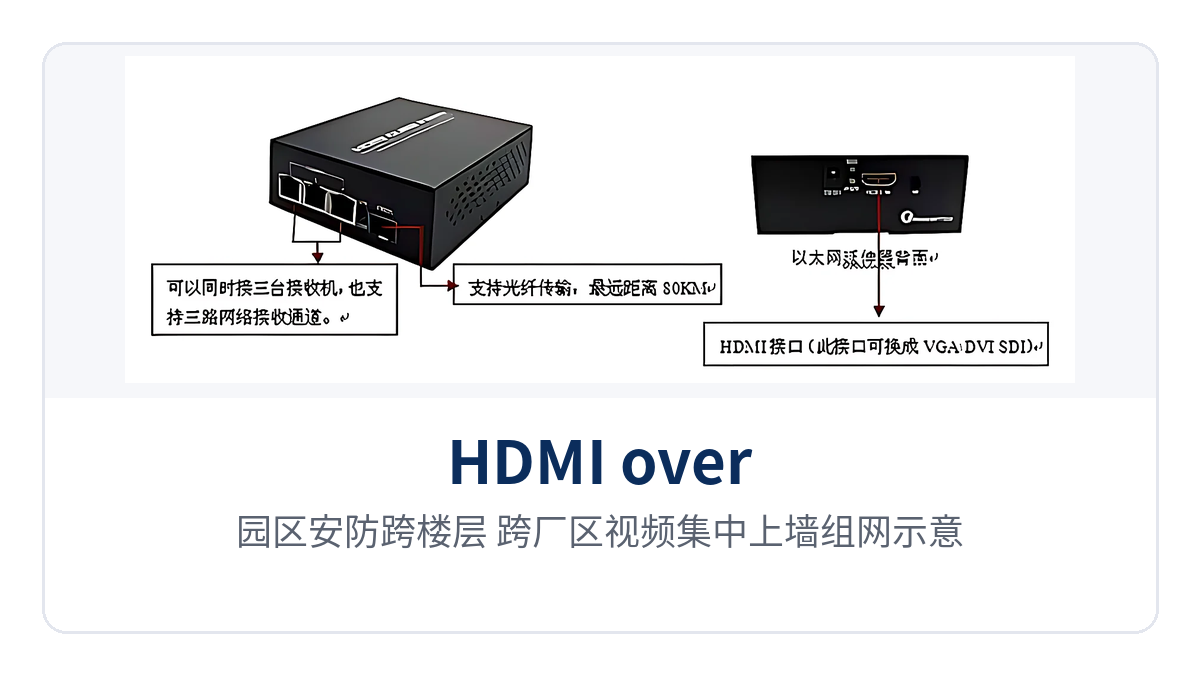
Figure 3: Schematic of centralized video display on screens across floors and plants in industrial park security
Industrial private networks and industrial park security: centralized display on screens across floors and plants
Cameras in plants and industrial parks are distributed at gatehouses, workshops, warehouses, and the perimeter, while the surveillance center is usually located in the office building. The extender converts HDMI or SDI images at the front end into IP data and uploads them to the center through the park's existing switches, eliminating the need to run separate video cables across floors and plants. In retrofit projects, a more convenient approach is to reuse the existing structured cabling and switch ports, adding only transmitters at the front end and receivers at the center. If the site already has a backbone network provided by an industrial Ethernet switch manufacturer, the extender can connect directly without additional modification.
The one-to-many capability under the same VLAN allows one image to be sent simultaneously to the large display in the duty room, the small screen at the security post, and the display end in the conference room, with the number of receivers increased as needed. New sites occupy only switch ports and IP addresses without changing existing links. For industrial parks built in phases, a few channels can be deployed first and expanded later, without rebuilding the network side.
Rail transit and energy and electric power: video backhaul and dispatch monitoring within private networks
The communication private networks between rail transit stations, substations, and energy station sites use Ethernet and optical fiber as the backbone, with video backhaul being one of the services. The extender feeds images from platforms, passages, and equipment areas into the private network for simultaneous display at the dispatch center and duty room; the cross-switch transmission approach matches the layered structure of the private network, eliminating the need to open a separate channel for video.
Long-distance sections are carried over optical fiber links, while network cable connects cameras and display ends at the station ends, with the medium switched on the switch side. The latency specification of less than 200 ms keeps the picture seen by dispatchers essentially synchronized with on-site actions, meeting the needs of monitoring and response decisions. Power supply, cabinet space, and grounding follow the standards of the respective professional equipment rooms, and the device itself is designed to industrial grade for continuous operation.
Unattended sites and long-distance transmission: less maintenance, fewer site visits
Equipment rooms at unattended sites are unmanned year-round, and once video equipment fails, troubleshooting must wait for personnel to arrive on site. The industrial-grade extender supports long-term uninterrupted operation; between the transmitter and receiver there is only a network link, with no analog stages requiring periodic calibration, so O&M actions focus on checking switch port status and device indicator LEDs, and the troubleshooting path is shorter than that of analog video links.
When sites are far apart and optical fiber resources are scarce, first check whether existing links can be reused: segments reachable by Ethernet use network cable, and segments beyond network cable distance use optical fiber, with no additional devices inserted in between. This approach breaks long-distance transmission into several maintainable segments, so fault location pinpoints a specific segment and emergency repair does not require testing the entire link segment by segment. During selection, plan uniformly across the product lines of optical multiplexer manufacturers such as Raytrans and industrial Ethernet switch manufacturers, so that video optical multiplexers and cross-switch Ethernet extenders each play their role and form a complete video transmission solution.
How to network one-to-many? Single-VLAN multiple receivers and thousands of channels switching
The prerequisite for one-to-many networking is that both ends are in the same VLAN, with no Layer 3 isolation across network segments on the switch. One transmitter encapsulates the image into a video stream and sends it to the network, and multiple receivers in the same VLAN each take the stream and decode it, so the same image can be played simultaneously on multiple display ends, forming flexible product showcase and dispatch screens. In engineering practice, receivers are placed in the service VLAN and management addresses use a separate segment, avoiding mixing with the office network during later expansion.
When the number of receivers increases, calculate the access bandwidth of switch ports and the uplink bandwidth. When there are many image channels, estimate the total by multiplying the bit rate per channel by the number of channels, then check whether the uplink port of a single switch is sufficient. Distributing receivers within a VLAN across multiple access switches and aggregating them via uplink links is more reliable than connecting them all to one switch, and the impact of a single device failure is also smaller.
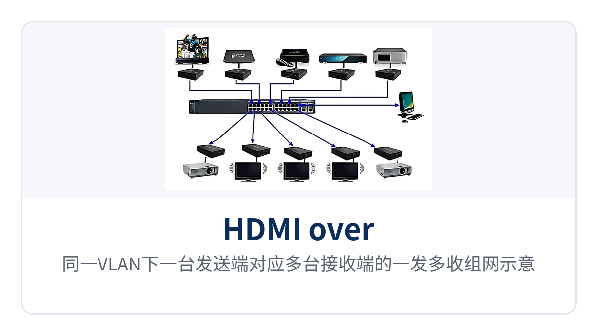
Figure 4: One-to-many networking schematic with one transmitter corresponding to multiple receivers in the same VLAN
With a distributed IP matrix, multiple transmitters and receivers are incorporated into the same management platform, and the operator switches any video channel to any display screen as required. Switching of thousands of video channels depends on the matrix scale and the switching network capacity; the actual number of accessible channels is subject to the project configuration and confirmation with the optical multiplexer manufacturer. Do not quote theoretical values directly at the solution stage.
How are Ethernet and optical fiber hybrid transmissions connected?
Ethernet and optical fiber hybrid transmission means that the same service chain contains both electrical-port Ethernet segments and optical fiber segments. Video comes out of the transmitter on the camera side and is first fed into the access switch; the access switch uplinks to the central switch through optical ports, and on the central side the receiver decodes and outputs the video to the display end. The medium is switched on the switch, so the cross-switch Ethernet extender itself does not need to change interfaces, nor does it need an additional pair of devices for optical-to-electrical conversion.
When the distance between sites exceeds the reach of network cables, this segment is carried by media converters or switches with optical ports, and both ends still use standard Ethernet frames. In engineering, the wavelength, transmission distance and optical fiber type of the optical module are calculated segment by segment along the link; single-mode and multi-mode are not mixed, and patch cord polarity is checked against the device markings. The specific optical module configuration is subject to the technical documentation supplied with the unit and the project list.
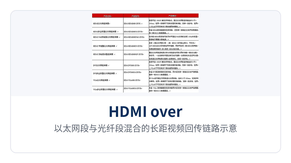
Figure 5: Schematic of a long-distance video backhaul link mixing Ethernet segments and optical fiber segments
Selection and deployment points
Start selection by counting three things: which video interfaces are available on site, how many levels of switches sit between the transmitter and the receiver, and how many display screens there are at the display end. Once these three are fixed, the matching switch ports, optical modules and number of receivers are determined. Deployment proceeds in the following order, and each step has a verifiable result, so problems need not wait until the whole link is powered on to be discovered.
- Interface check: count the interface types of front-end cameras and signal sources, and how many channels of HDMI, DVI, VGA, SDI and CVBS there are respectively, then determine the number of transmitters and the interface form accordingly.
- Switches and VLANs: confirm which level of switch the transmit and receive ends are connected to, define the service VLAN, and separate video streams from management traffic to avoid receiving no stream due to cross-network-segment issues.
- Bandwidth calculation: estimate the total bandwidth by multiplying the bit rate per channel by the number of video channels, check the margin of access ports and uplink ports, and in cases with many receivers, distribute the traffic across devices provided by multiple industrial Ethernet switch manufacturers.
- Optical fiber links: use optical fiber for segments beyond the network cable distance, check the optical module wavelength, distance and optical fiber type, and connect patch cord polarity according to the device markings.
- Display end and audio: confirm the interface and cable length from the receiver to the display screen, and check the interface form and level when audio is connected separately to the sound reinforcement system.
- Power-on verification: first establish single-point connectivity, then expand point by point, check the indicator LEDs, switch port status and actual image, and finally spot-test the latency and multi-screen simultaneous display effect.
Conclusion
As a cross-switch Ethernet extender, the IDM-HD680X-DT/R combines video interface compatibility, one-to-many transmission and Ethernet and optical fiber hybrid transmission in a single pair of transmit and receive devices. It addresses the on-site problem of a video source and a display end separated by switches, by floors and by several kilometers, rather than extending the transmission distance of a point-to-point video optical multiplexer a bit further. In engineering, the existing structured cabling is reused, and each additional video channel only occupies switch ports and bandwidth.
For industrial private networks, industrial park security surveillance and unattended sites, the value of this connection approach lies in reusing the existing network: no civil works, no repeaters, and no separate laying of video cables. The two capabilities of latency less than 200ms and industrial-grade uninterrupted operation determine whether it can stay for a long time in an unattended cabinet, and also determine whether dispatchers are willing to entrust key images to it. Raytrans has long been engaged in the field of optical multiplexers and video transmission, providing reliable optical multiplexers and supporting networking solutions for various industrial and security surveillance projects.