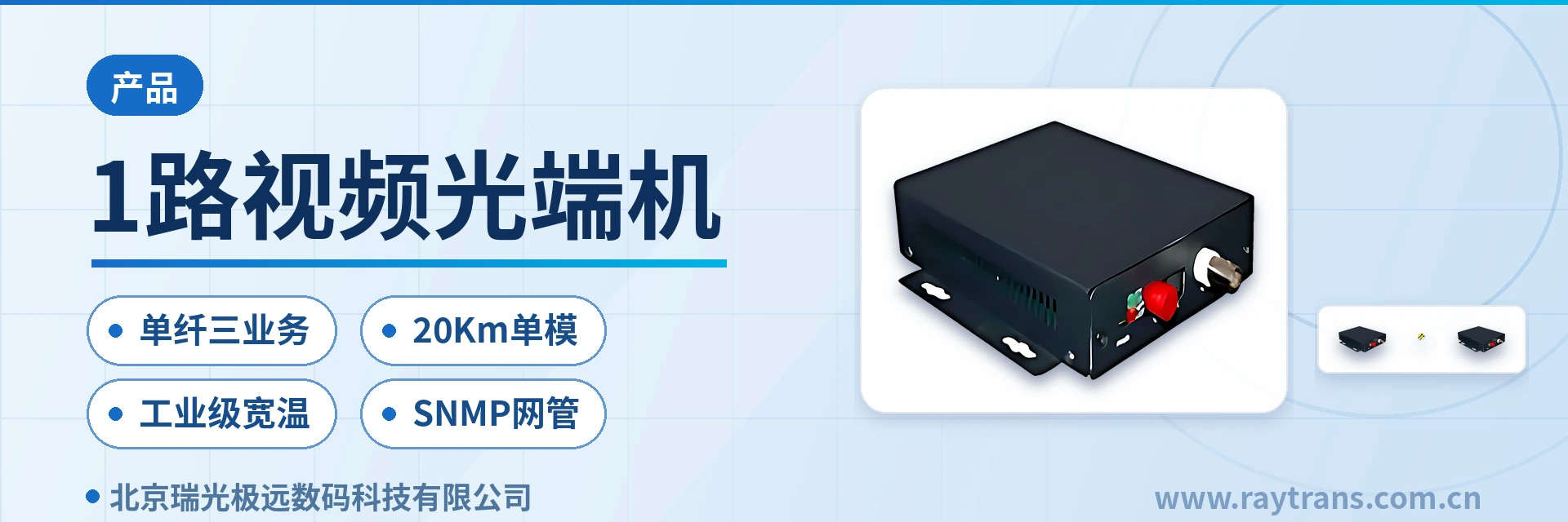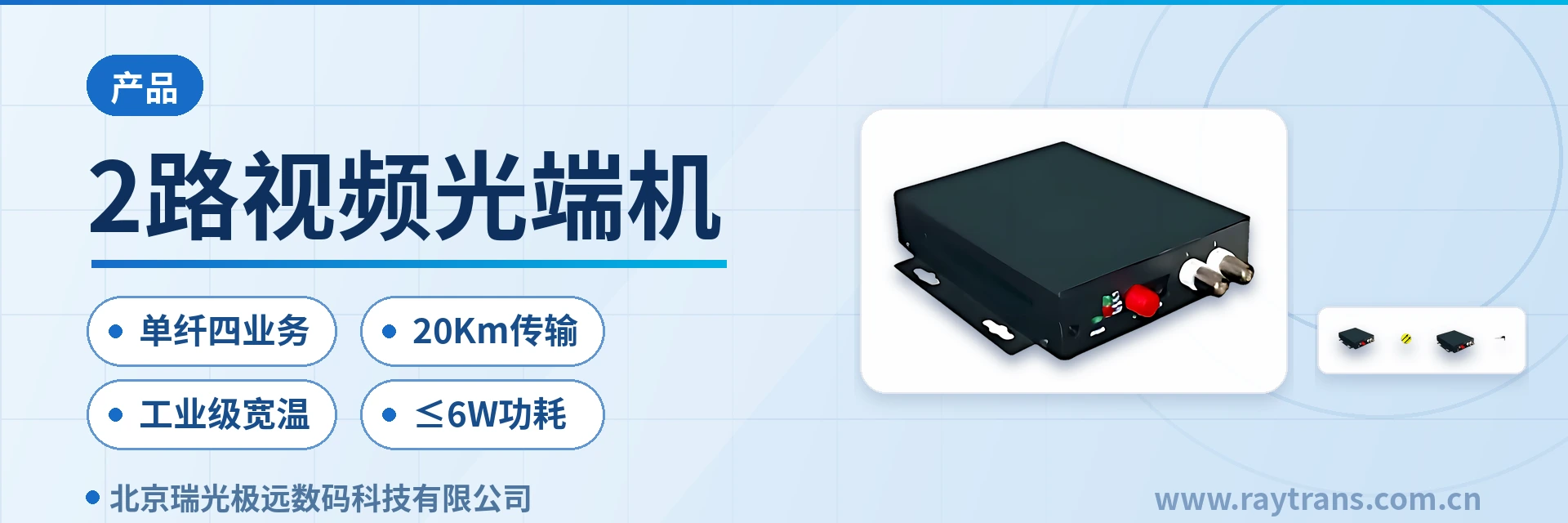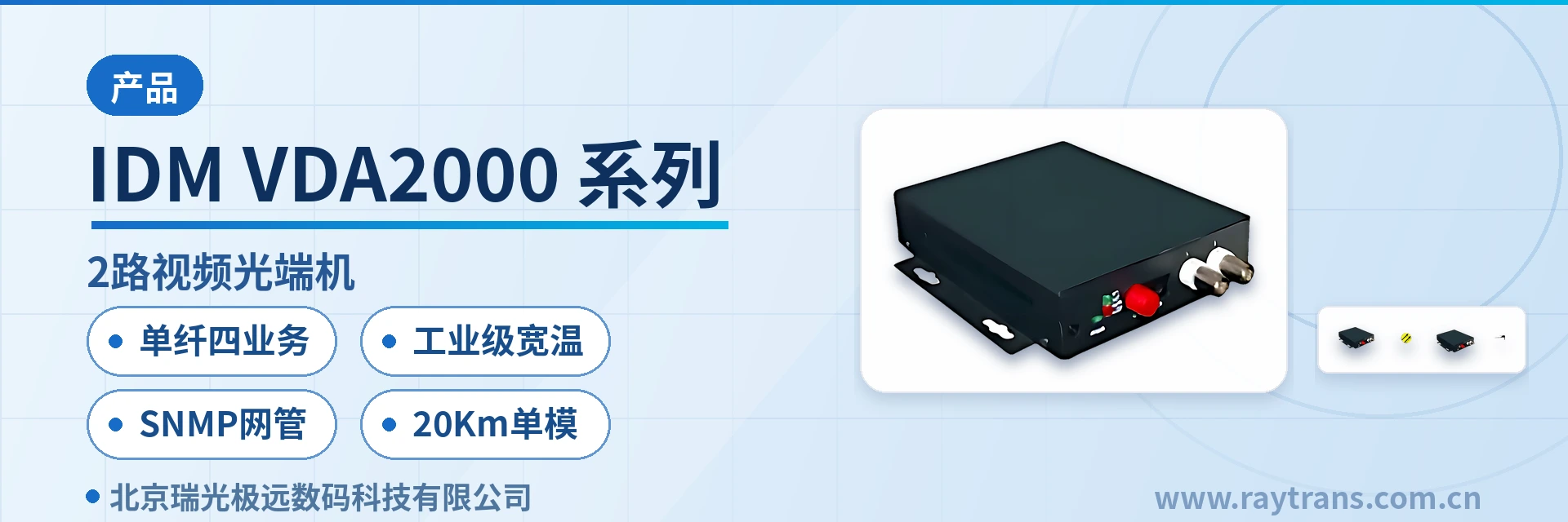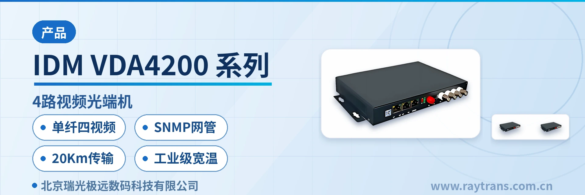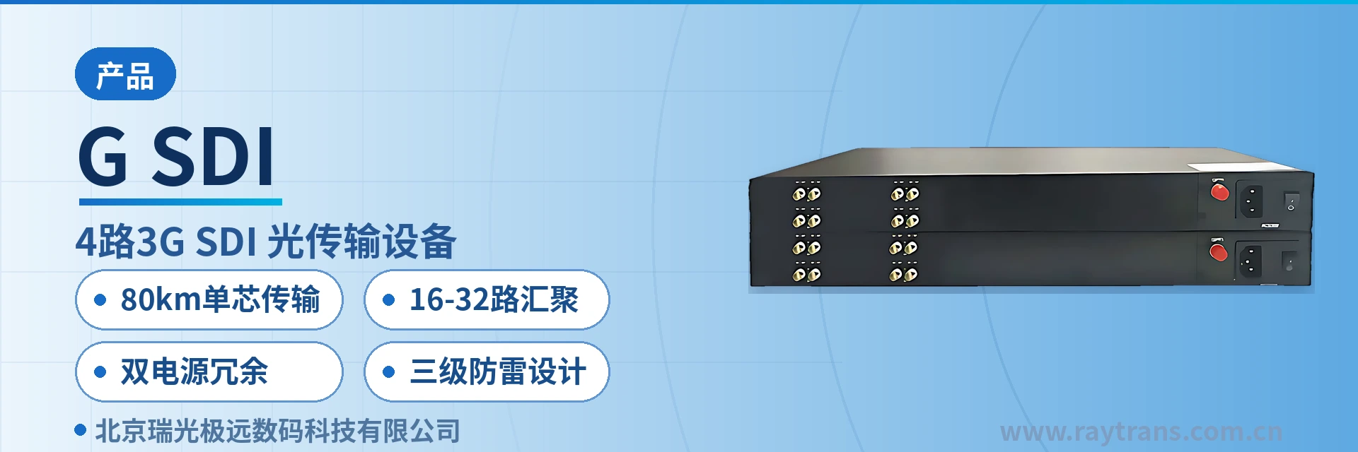
G-SDI 4-Channel 3G-SDI Optical Multiplexer
1~8-channel SDI, audio, Ethernet single-fiber backhaul, 16~32-channel aggregation, plug-and-play
4-channel 3G-SDI optical transmission equipment, all-digital, uncompressed, high-definition optical fiber transmission, supports 1–8-channel 3G/HD/SD-SDI serial digital video and 1–8-channel audio line transmission, supports rates from 19.4 Mbps to 1.485 Gbps
3G-SDI optical transmission equipment is an access device that transmits 3G/HD/SD-SDI serial digital video signals over optical fiber in an all-digital, uncompressed manner, and is used in pairs consisting of a transmitter and a receiver. In private networks such as broadcasting, security surveillance, and electric power and energy, it handles the video backhaul task from the site to the equipment room, and the restored output at the receiver can be fed directly into switchers, matrices, or video recording equipment. It is a typical application form in the product showcase of video optical multiplexers.
The device is compatible with the SMPTE 259M, 292M, 344M, and 424M serial digital video standards and the ITU serial digital video standard, covering a rate range of 19.4 Mbps to 1.485 Gbps. 3G-SDI, HD-SDI, and SD-SDI signals are accessed on the same link according to their actual bit rates, and front-end devices do not need to change interface modules for format differences.
As a 3G-SDI video optical multiplexer, it aggregates video with audio, data, Ethernet, and other services onto a single optical fiber, reducing the number of cables and the wiring workload from the site to the equipment room, and also preventing cable trunking from being filled by multiple cable runs. Adding services later does not require laying new optical cables. This multi-service optical multiplexer form has deployment value in government private network optical fiber communication solutions, military emergency communications vehicle solutions, and smart mining communication solutions. As an optical multiplexer manufacturer, Raytrans can provide selection and technical support for the corresponding models.
Key Specifications at a Glance: 1–8-channel 3G/HD/SD-SDI · 1–8-channel audio · 19.4 Mbps–1.485 Gbps · single-fiber 80 km · 16–32-channel aggregation · DC 5V/12V/24V compatible power supply
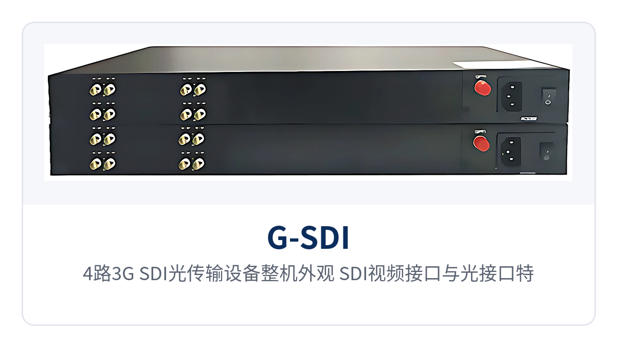
Figure 1: Overall appearance of the 4-channel 3G-SDI optical transmission equipment, with a close-up of the SDI video interfaces and optical interfaces
What services can the 4-channel 3G-SDI optical transmission equipment access
4-channel 3G-SDI refers to the common configuration in which a single device carries 4 channels of SDI video; actual ordering can select between 1 and 8 channels, and audio channels are configured synchronously at 1 to 8 channels. In addition to SDI video, the device also supports access of analog AV signals, data, Ethernet, and telephone signals, so existing on-site surveillance, intercom, and control services do not require additional cabling. As a professional optical multiplexer manufacturer, Raytrans also presents this multi-service access capability as a core configuration in its product showcase of video optical multiplexers and multi-service optical multiplexers.
The functions are listed item by item in the table below, and each item corresponds to a capability that can be verified on site. During ordering, simply check each item according to the services at the site. Once the number of SDI video and audio channels, whether data and Ethernet services are overlaid, and the front-end power supply format are confirmed, the port configuration is determined accordingly. On site, connect cables according to the port markings; no electrical or optical adjustment is required.
| Function | Description |
|---|---|
| 1–8-channel SDI video transmission | A single device carries 1–8 channels of 3G/HD/SD-SDI serial digital video, acquired at the transmitter and restored and output at the receiver |
| 1–8-channel audio transmission | Audio is transmitted over the same fiber as video, and is backhauled or sent downstream together with the video channel |
| All-digital uncompressed | Video undergoes no compression encoding or decoding; the original digital stream is sent over the optical fiber, and picture details are not lost after restoration |
| Automatic cable equalization | A built-in automatic cable equalizer compensates for the high-frequency attenuation caused by front-end SDI coaxial cables |
| Clock retiming | A built-in clock retiming function reshapes signal jitter after transmission over long cables |
| Multi-service access | Supports access of analog AV signals, data, Ethernet, and telephone signals on the same link |
| Wavelength division multiplexing | Supports WDM, CWDM, and DWDM technologies, with multiple signals sharing optical fiber resources by wavelength |
| Plug-and-play | No software setup is required, hot-swappable, and replacing boards or adding services does not require shutdown for configuration |
| Chassis aggregation | The dual power supply plug-in card aggregation chassis supports 16–32-channel aggregation; add plug-in cards according to the number of sites |
| Multiple power supplies | DC 5V, 12V, and 24V compatible input, adapting to different front-end power supply conditions |
| Surge and ESD protection | Built-in surge and ESD protection, three-level lightning protection design |
| Industrial-grade structure | 19-inch rack-mounted or standalone structure, suitable for extremely high and extremely low temperature industrial environments |
Transmission performance and technical specifications
The transmission capability of the device centers on three items: rate range, optical fiber distance, and aggregation scale. For detailed electrical and mechanical items, the manufacturer's technical documentation shall prevail. The table below lists parameters and applicable conditions by item. During engineering calculation, use the actual optical cable attenuation and number of sites; for long-distance links, first perform an optical power budget and then determine the optical module.
| Item | Parameter/Specification | Description/Applicable Conditions |
|---|---|---|
| Video channel | 1–8-channel 3G/HD/SD-SDI | Number of channels determined by ordering configuration; 4 channels is the common configuration |
| Audio channel | 1–8-channel audio | Transmitted over the same fiber as video |
| Transmission rate | 19.4 Mbps–1.485 Gbps | Covers the actual bit rates of SD-SDI, HD-SDI, and 3G-SDI |
| Compatible standards | SMPTE 259M, 292M, 344M, 424M, ITU serial digital video standard | Access is possible as long as the front-end device output standard is consistent |
| Transmission medium | Single-fiber gigabit optical fiber | Single-mode and multi-mode optional |
| Transmission distance | 80 km over a single optical fiber | Related to the optical module and optical cable attenuation; calculated according to the optical power budget |
| WDM capability | WDM, CWDM, DWDM | Plan wavelengths when multiple signals share an optical fiber |
| Signal processing | Automatic cable equalization, clock retiming | Compensates for long cable attenuation and reshapes clock jitter |
| Service expansion | Analog AV, data, Ethernet, telephone | Transmitted on the same link as SDI video |
| Power supply | DC 5V, 12V, 24V compatible input | Front-end sites select according to existing power supply conditions |
| Chassis aggregation | Dual power supply plug-in card chassis, 16–32 channels | Centralized aggregation in the central equipment room; power supplies configured in dual-channel mode |
| Structure | 19-inch rack-mounted or standalone | Rack-mounted in the equipment room or standalone installation at the front end |
| Protection | Built-in surge and ESD protection, three-level lightning protection design | Outdoor and industrial sites still require grounding according to specifications |
| Operating environment | Suitable for extremely high and extremely low temperature harsh industrial environments | Specific temperature range: not yet recorded in the knowledge base |
| Optical interface type, power consumption, overall dimensions | Not yet recorded in the knowledge base | The manufacturer's technical documentation shall prevail |
Why all-digital uncompressed determines picture quality
All-digital uncompressed transmission means that after the SDI signal completes cable equalization and clock retiming at the transmitter, the original digital stream is sent directly over the optical fiber. There is no compression encoding or decoding stage in the link, and what the receiver restores is the original picture data of the front-end device; the link introduces no processing latency caused by compression algorithms.
SMPTE 259M, 292M, 344M, and 424M respectively specify the interface characteristics of different grades of serial digital video. The device accesses signals according to the rate ranges of these standards, and SDI signals output by cameras, switchers, and non-linear editing workstations can enter the fiber without transcoding; the picture undergoes no reconstruction on the link.
The automatic cable equalizer addresses the attenuation problem of front-end coaxial cables: after SDI signals pass through tens of meters of cable, the high-frequency components are noticeably attenuated. The equalizer compensates for the amplitude-frequency characteristics according to cable length, so that the eye diagram entering the device opens up again. Clock retiming then reshapes the clock and data phase of the signal after equalization, suppressing jitter introduced by long cables and connectors and providing a clean stream for subsequent optical modulation.
Both processes are completed inside the device, and no adjustment knobs are exposed on site, so link commissioning only requires connecting cables according to the port markings. The stability of SDI video optical fiber transmission mainly depends on the optical fiber link itself. As long as sufficient margin is reserved in the budget for optical cable attenuation, splice points, and connector loss, the picture remains stable over the long term. In the product showcase of Raytrans video optical multiplexers, all-digital uncompressed is also described as a key indicator of picture quality assurance.
Differentiated capability: how 80 km single-fiber transmission and 16–32-channel aggregation are implemented
The on-site value corresponding to the four capability labels is listed in the table below, which can be used during selection to judge whether the device matches the current project. The judgment order is to first check whether the single-segment link distance falls within the single-fiber 80 km range, then check the number of sites that need to be aggregated at the central side, and then verify the equipment room power supply and outdoor lightning protection conditions.
| Selling Point | Corresponding Capability | On-site Value |
|---|---|---|
| 80 km single-fiber transmission | 80 km over a single optical fiber, single-mode and multi-mode optional | Wide-area private networks and remote stations do not need intermediate repeaters; video backhaul is completed over one fiber core |
| 16–32-channel aggregation | Dual power supply plug-in card aggregation chassis supports 16–32-channel aggregation | Front ends are deployed in a scattered manner by site, and the central side aggregates centrally in a chassis; capacity expansion only requires adding plug-in cards |
| Dual power supply redundancy | Dual power supply configuration for the aggregation chassis; an abnormality in one power supply does not affect services | Services continue to run during equipment room maintenance or when one power supply loses power |
| Three-level lightning protection design | Built-in surge and ESD protection, three-level lightning protection design | Reduces port damage caused by lightning surges at outdoor pole-side and industrial sites |
Networking and deployment: how to configure point-to-point access and chassis aggregation
A pair of 3G-SDI optical multiplexers forms a point-to-point link. The front-end device and the equipment room receiver are connected according to port markings, and the optical module models and wavelengths at both ends of the link must be consistent. When multiple front-end sites need to be backhauled to the center, configure a dual power supply plug-in card aggregation chassis in the central equipment room instead; the front ends still access in point-to-point mode, and the central side aggregates centrally. This networking approach has mature applications in government private network optical fiber communication solutions, military emergency communications vehicle solutions, and smart mining communication solutions. Raytrans can provide corresponding optical multiplexer selection and deployment recommendations according to the project scenario.
- Point-to-point link: the front-end transmitter connects to the SDI output of a camera or switcher, and the equipment room receiver output connects to matrices and video recording equipment;
- Central aggregation: the chassis is configured with plug-in cards at a scale of 16–32 channels; when sites increase, expand capacity by adding plug-in cards, and the chassis power supply is connected in dual-channel mode;
- Optical fiber selection: single-mode and multi-mode are selected according to the existing optical cable; when multiple signals need to share a fiber core, plan wavelengths according to WDM, CWDM, and DWDM;
- Front-end power supply: DC 5V, 12V, and 24V compatible input, selected according to the existing power supply at the site; no separate power supply modification is required for the device;
- Commissioning and maintenance: no software setup is required, hot-swappable, and replacing plug-in cards or adding service boards does not require shutdown for configuration.
Two points also require attention on site: the connector workmanship of SDI coaxial cables directly affects the equalization margin, and poor crimping of BNC connectors can cause momentary picture interruptions; even though the device has a built-in three-level lightning protection design at outdoor sites, equipotential bonding of cabinets and grounding resistance must still be implemented according to engineering lightning protection specifications.
Typical application scenarios
The device addresses three types of scenarios: broadcasting and new media, security surveillance and rail transit, and electric power and energy industrial private networks. What they have in common is scattered video sources, long link distances, and inconsistent on-site power supply conditions. The following describes deployment points and configuration notes by industry. The three types of scenarios place different emphasis on picture quality, latency, and link reliability; during selection, determine the configuration according to the most demanding requirement among them. As a professional optical multiplexer manufacturer, Raytrans provides corresponding configuration recommendations for different industries in its product showcase.
Broadcasting and new media
SDI signals between studios, outside broadcast vans, and venues require low-latency, lossless backhaul. Compression encoding introduces processing latency and picture quality loss, while the distance from the site to the equipment room is often hundreds of meters or even several kilometers of campus optical cable. The 3G-SDI video optical multiplexer sends 1–8 channels of SDI video and audio over a single optical fiber in an all-digital uncompressed manner, and the restored output at the receiver goes directly into switchers and monitoring and recording equipment.
Temporary broadcast sites for competitions and events also often require rapid deployment. The device requires no software setup and is hot-swappable, so on-site commissioning only requires connecting cables according to the ports; the single-fiber 80 km transmission capability eliminates the need for a repeater equipment room between remote camera positions and the main control equipment room, reducing the investment in temporary cabinets and power supply points.
Security surveillance and rail transit
Surveillance sites along Safe City, expressway, and rail transit lines are scattered, the distance from the front end to the road section center or command center is long, and the electromagnetic environment along the line is complex. Coaxial cable solutions suffer attenuation and interference after several hundred meters. The device supports analog AV signal access, so existing standard-definition surveillance systems can continue to be used, and upgrades can replace them in batches by site.
Rail transit and expressway scenarios also require centralized management at the central side. Video from multiple sites is sent up through point-to-point links and then aggregated by the dual power supply plug-in card chassis; the 16–32-channel aggregation scale matches the number of road section monitoring points. The built-in surge and ESD protection and three-level lightning protection design adapt to the lightning surge environment of pole-side cabinets along the line.
Electric power and energy industrial private networks
Substations, new energy stations, and industrial sites in mining and oil and gas fields span wide temperature ranges and face strong electromagnetic interference, so video surveillance and device status backhaul require links that operate stably over the long term. The equipment is industrial-grade by design and suits harsh industrial environments with extremely high and extremely low temperatures. Optical fiber transmission itself is immune to electromagnetic interference and common-ground loops, and can reliably deliver in-station SDI video to the centralized control station.
Where front-end sites use different power supply formats, DC5V, 12V, and 24V compatible inputs can draw directly from the station's direct current power supply, eliminating the need for a dedicated power supply module for the equipment. The central centralized control station aggregates video from all sites through a dual power supply card-based chassis, so services remain uninterrupted when one power supply fails, reducing picture loss caused by power supply inspection. For typical requirements such as government private network optical fiber communication solutions, military emergency communications vehicle solutions, and smart mining communication solutions, Raytrans can provide combined deployment of multi-service optical multiplexers and video optical multiplexers; for specific product showcase and selection parameters, technical documentation is available from the optical multiplexer manufacturer.
Conclusion
3G-SDI optical transmission equipment aggregates 1 to 8 channels of SDI video with audio, data, and Ethernet services onto a single optical fiber, transmits in an all-digital uncompressed manner, and supports 80 km over a single-fiber. The central side uses a dual power supply card-based chassis to aggregate 16 to 32 channels, while the front end draws power through DC5V, 12V, and 24V compatible inputs, adapting to deployment conditions in wide-area private networks and remote stations.
For the three types of users—broadcast and television, security surveillance, and electric power and energy—the key to selection is to first confirm the number of front-end SDI channels, the optical cable distance, and the central aggregation scale, and then determine the number of optical modules and chassis plug-in cards accordingly. The optical interface type, overall power consumption, and specific operating temperature range are subject to the manufacturer's technical documentation; at the solution stage, the configuration is confirmed after calculation based on the actual link. As an optical multiplexer manufacturer, Raytrans can provide product showcase and technical support for multi-service optical multiplexers and video optical multiplexers in government private network optical fiber communication solutions, military emergency communications vehicle solutions, and smart mining communication solutions.